SwarmSight Appendage Tracking Output File Column Reference
The .CSV file saved by the SwarmSight Appendage Tracking module contains a set of columns with values of measurements obtained from the processed video.
.CSV File Location
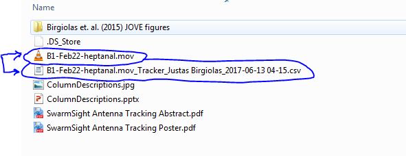
By default, the software saves the .csv file in the same folder as the video file. It appends “Tracker”, the name of the logged in user, date, and time to the file name.
.CSV File Columns
The .csv file can be read by most statistical analysis software. Below, it was opened with Excel.
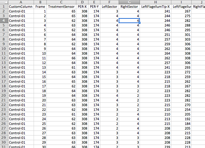
The following table describes each column in detail. All X,Y coordinates are in video pixels and use the standard video coordinate system, where (0,0) is the top left pixel of the video, X values increase towards the right side of the screen, and Y values increase towards bottom of the screen. For example, X=20 and Y=50 can be interpreted as a point 20 pixels from the left side of the video and 50 pixels from the top.
| Column Name | Description |
|---|---|
| CustomColumn | Contains a custom value that can be set by the user in the “Save” section in the right panel. |
| Frame | Frame number. Starts with 1. Time can be determined by dividing this value by the video frame rate (e.g. 30 fps). |
| TreatmentSensor | Brightness value of the pixel in the center of the “Treatment Sensor”. Value ranges between 0 and 255, with 255 indicating maximum brightness. |
| PER-X/Y | The X,Y position of the detected proboscis. If no proboscis is detected, the X,Y values will point to the edge of the mandibles. |
| PER-Length | The normalized length of the proboscis. The value will range between 0-50 and will not depend on scale. Units are arbitrary. |
| Left/RightSector | The 36 degree sector (1-5) on either side of the head, which contained the largest number of “likely antenna” points. Can be useful if antenna x, y measures are too noisy. This is the coarsest, but most reliable antenna orientation measure. |
| Left/RightSectorMode | The angle in degrees with the strongest activation by likely antenna points. The angle is measured from the midpoint of the bases of the scape (“the center of the head”). This measure is always positive and does not take the position of the flagellum base into account. |
| Left/RightAngle | The angle in degrees formed by the detected tip and base of the flagellum. This measure reflects the orientation of the flagellum most accurately, but is sensitive to problems detecting the flagellum tip or base locations, and can be more noisy than the Mode and Sector measures. Using a 3-frame rolling median filter can reduce the noise. |
| LeftFlagellumTip-X/Y | The X,Y position of the tip of the antenna in the video frame. |
| LeftFlagellumBase-X/Y | The X,Y position of the part of the flagellum that did not overlap the head (see diagram below). |
| RightFlagellumTip-X/Y | See LeftFlagellumTip-X/Y. |
| RightFlagellumBase-X/Y | See LeftFlagellumBase-X/Y. |
| RotationAngle | The angle, in degrees, that the head was rotated. 0 means the head pointed directly to the top of the screen. Positive values indicate clockwise rotation, negative - counterclockwise. |
| AntennaSensorWidth | The width, in video pixels, of the boundaries of the square Antenna Sensor widget. Yellow dot (see below) is directly in the middle of the sensor. |
| AntennaSensorHeight | See AntennaSensorWidth. Currently, Height = Width. |
| AntennaSensorOffset-X/Y | X value indicates the distance between the left-most edge of the video to the left-most edge of the AntennaSensor widget (see below). Y value: distance from top of video to top edge of the widget. |
| AntennaSensorScale-X/Y | Scale factor of the AntennaSensor in arbitrary units. Currently, X = Y. |
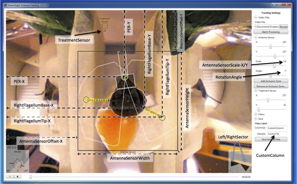
Below is a visual description of each column.